This radio was sold as a home construction
kit to its adherents by a Dutch broadcasting organisation (KRO).
It was built by Cornelis Tol from Zaandam in the Netherlands in
1932 or 1933 and donated to my collection by his grandson.
|
The radio covers
two bands (with automatic switching): 200-600 and
1000-2000 meter.
|
 |
|
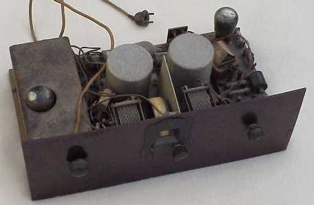
Radio as acquired |
||
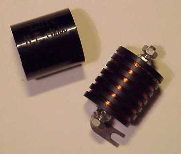 |
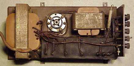
I decided to dismantle the radio completely and cleaned all parts (including the 50 pieces of wire).I repaired one of the HF-chokes as it appeared to be interrupted. The left picture shows the choke in opened up situation.In stead of the LF-choke a resistor of 80 kohm was mounted, upon recommendation of the article mentioned above. |
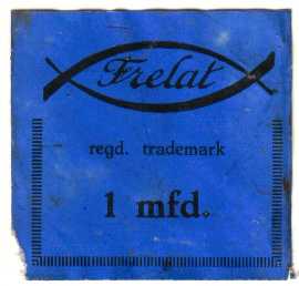
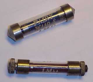
All resistors were built in glass tubes (right picture) and very far off from original values. As I did not manage in opening up the tubes and replace the interior, I replaced the resistors entirely by species with the proper value but from different construction.Several capacitors were built in similar housings, but with plastic in stead of glass tubes. Those could easily be opened and new high quality components inserted.All block capacitors were emptied, filled with new components and closed again (label on capacitors shown left). |
 |
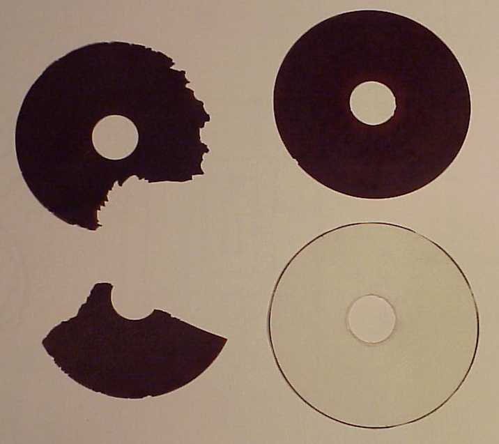
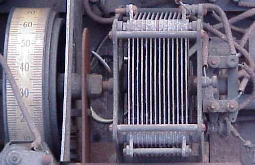
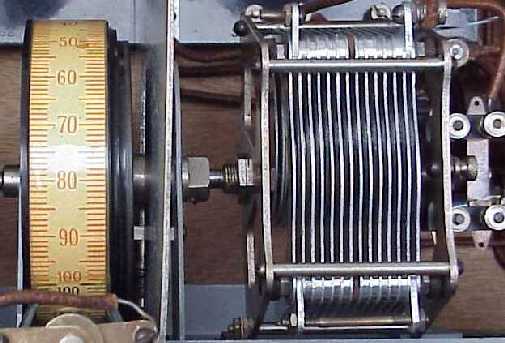
Both tuning
capacitors were dismantled and cleaned. The pictures at
the right hand side show one of the capacitors before and
after treatment. |
 |
 |
 |
|
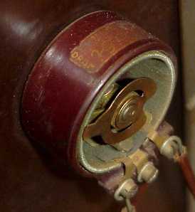 |
The isolation
of the variable antenna capacitor was severely damaged
(right picture), which resulted in a short circuit. The potentiometer was replaced by a type with an appearance more close to the original one. A picture of the original potentiometer with a resistance of 400 ohm is shown at the left. I still hope to find the original part some day.
|
|
After having mounted all parts and wires again (in accordance with the detailed instructions in the original manual), powering up the radio and connecting a high impedance loudspeaker, several stations could be heard. |
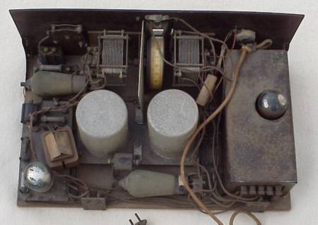
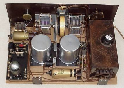
Radio before restoration and after ................
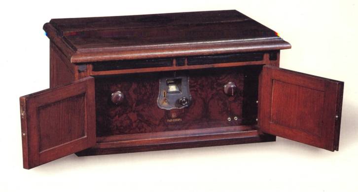
Radio in cabinet (courtesy Radiomuseum Reusel, Netherlands)